English
 Español
 Deutsch
  Italia
  日本語
日本語 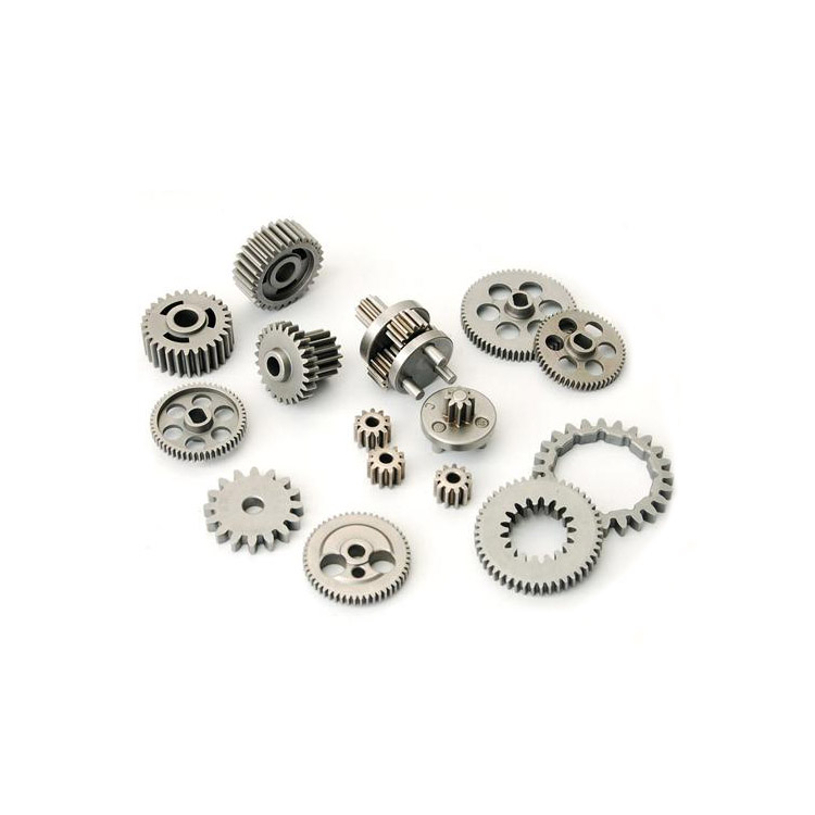
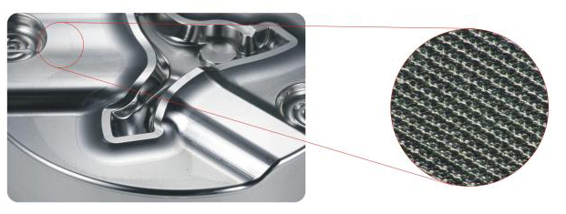
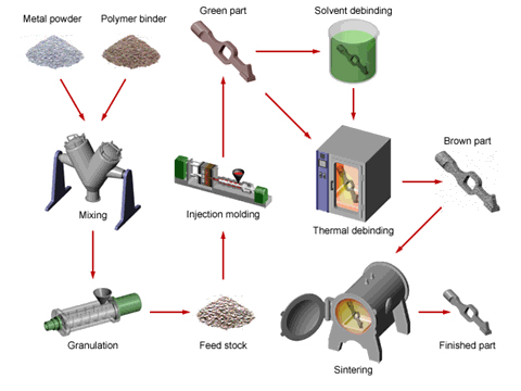
Metal Injection Molding (MIM) is a variation on traditional plastic injection molding that enables the fabrication of solid metal parts utilizing injection molding technology. In this process, the raw material, referred to as the feedstock, is a powder mixture of metal and polymer. For this reason, MIM is sometimes referred to as Powder Injection Molding (PIM). Using a standard injection molding machine, the powder is melted and injected into a mold, where it cools and solidifies into the shape of the desired part. Subsequent heating processes remove the unwanted polymer and produce a high-density metal part.
Metal injection molding is best suited for the high-volume production of small metal parts. As with injection molding, these parts may be geometrically complex and have thin walls and fine details. The use of metal powders enables a wide variety of ferrous and non ferrous alloys to be used and for the material properties (strength, hardness, wear resistance, corrosion resistance, etc.) to be close to those of wrought metals. Also, because the metal is not melted in the MIM process (unlike metal casting processes), high temperature alloys can be used without any negative affect on tool life.
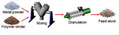
◆ Feedstock preparation - The first step is to create a powder mixture of metal and polymer. The powder metals used here are much finer (typically under 20 microns) than those used in traditional powder metallurgy processes. The powder metal is mixed with a hot thermoplastic binder, cooled, and then granulated into a homogenous feedstock in the form of pellets. The resulting feedstock is typically 60% metal and 40% polymer by volume.
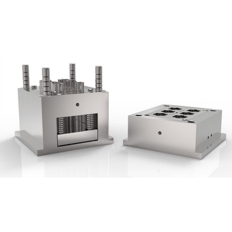
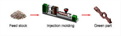
◆ Injection molding - The powder feedstock is molded using the same equipment and tooling that are used in plastic injection molding. However, the mold cavities are designed approximately 20% larger to account for the part shrinkage during sintering. In the injection molding cycle, the feedstock is melted and injected into the mold cavity, where it cools and solidifies into the shape of the part. The molded "green" part is ejected and then cleaned to remove all flash.
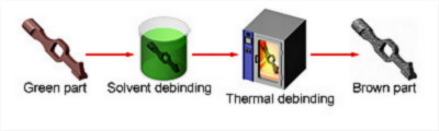
◆ Debinding - This step removes the polymer binder from the metal. In some cases, solvent debinding is first performed in which the "green" part is placed in a water or chemical bath to dissolve most of the binder. After (on in place of) this step, thermal debinding or pre-sintering is performed. The "green" part is heated in a low temperature oven, allowing the polymer binder to be removed via evaporation. As a result, the remaining "brown" metal part will contain approximately 40% empty space by volume.
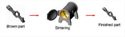
◆ Sintering - The final step is to sinter the "brown" part in a high temperature furnace (up to 2500°F) in order to reduce the empty space to approximately 1-5%, resulting in a high-density (95-99%) metal part. The furnace uses an atmosphere of inert gases and attains temperatures close to 85% of the metal's melting point. This process removes pores from the material, causing the part to shrink to 75-85% of its molded size. However, this shrinkage occurs uniformly and can be accurately predicted. The resulting part retains the original molded shape with high tolerances, but is now of much greater density.
◆ After the sintering process, no secondary operations are required to improve tolerance or surface finish. However, just like a cast metal part, a number of secondary processes can be performed to add features, improve material properties, or assemble other components. For example, a MIM part can be machined, heat treated, or welded.
Open small hole
◆ Material: PX5 (HRC30)
◆ Workpiece size: 30X30X50mm
◆ Tool: φ0.08HSS micro drill
◆ Processing conditions: S=40,000min-1; F=50mm/min; cutting amount 0.005mm
◆ Processing depth: 0.16mm (L/D=2)
◆ Number of processing holes: 675 holes (Mitsubishi symbol)
◆ Processing time: 2 hours and 37 minutes
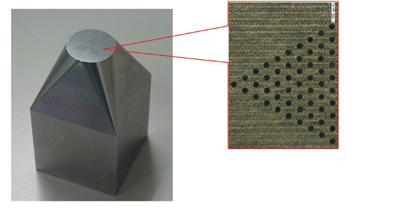
With one tool can complete the processing of 675 holes without burrs and deformation after processing.
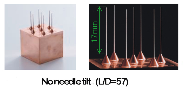
Copper Electrode Needle
◆ Material: Acid-free copper
◆ Workpiece size: 30X20X50MM
◆ Rough machining conditions: φ6 super hard milling cutter; S=8,000min-1; F=3,200mm/min; cutting amount 0.5mm
◆ Finishing conditions: D3R0.3 super hard ball cutter; S=6,400min-1
F=256min/min; cutting amount 0.02mm
◆ Toolpath: rough machining contour line; fine processing winding line
◆ Processing time: 21 minutes for rough machining; 5 hours and 22 minutes for fine machining
◆ Needle shape size: φ.3mmX0.5°; taper X length 17mm
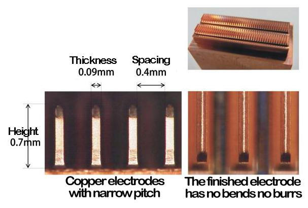
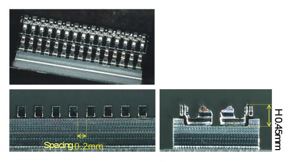
Copper electrode processing for narrow connectors
◆ Material: Copper pitch
◆ Workpiece size: 20X10X10mm
◆ Shape spacing: 0.4mm
◆ Using tool: super hard tool φ0.2 R0.05 ball knife
◆ Finishing conditions: S=40,000min-1; F=200mm/min; Allowance: 0.006mm; Cutting amount: 0.008mm
◆ Processing time: 8 hours and 20 minutes
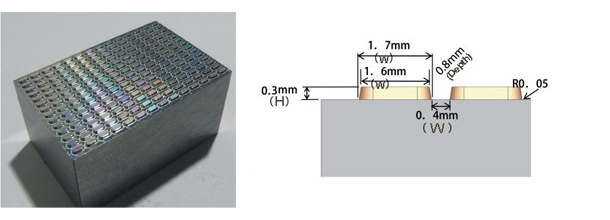
Processing of connector model
◆ Material: HAP10
◆ Workpiece size: 8X3X10 mm
◆ Pitch: 0.4mm
◆ Using tool: super hard tool R0.05 ball knife
◆ Finishing conditions: S=40,000min-1; F=40mm/min Machining allowance 0.002mm; Cutting amount 0.002mm
◆ Processing time: 16 hours and 20 minutes
The advanced connector mold processing greatly shortens the processing time compared with EDM (electrical discharge machining).
LED Mold
◆ Material: ELMAX (HRC60)
◆ Workpiece size: 30X20X15MM Number: 14X14=196
◆ Machining tool: R0.2CBN ball cutter D0.4 R0.05CBN milling cutter
◆ Processing conditions: S=40,000min-1, F=660mm/min; Cutting amount: 0.005mm; cutting spacing: 0.003mm
◆ Processing time: 7 hours and 9 minutes
Machining with super-hard tools effectively controls the wear of the tool, and even the multiple processing of small shapes can be processed with stable accuracy, shape and roughness.
Precision of the machined surface
◆ Spindle: Effectively avoid thermal deformation, high rigidity, low vibration
◆ Frame: High rigidity structure, low vibration of moving surface, damping capacity
◆ Feed shaft: High rigidity, low vibration